


AmpBird
DIY Battery Kit | DIY Kit
48V 280AH 314Ah Stackable DIY Battery Kit for Home Energy Storage 16S LiFePO4 System with JK BMS
48V 280AH 314Ah Stackable DIY Battery Kit for Home Energy Storage 16S LiFePO4 System with JK BMS
Couldn't load pickup availability
1. Build Your Own 48V Home Energy Storage Battery
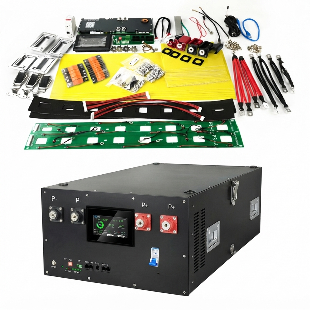
The AmpBird 16kWh 48V DIY Battery Kit includes nearly everything you need to assemble a professional LiFePO4 battery pack—except the battery cells.
Designed for DIY enthusiasts, solar installers, and home energy storage users, this complete kit helps you build a reliable 48V battery system using your preferred LiFePO4 cells.
Whether you're building a home backup battery, an off-grid energy system, or an RV power solution, AmpBird provides the essential components in one complete package.
2. What's Included
Your Kit Includes
✔ JK Smart BMS
✔ LCD Display
✔ DC Breaker
✔ Busbars
✔ PCB Board
✔ Epoxy Insulation Board
✔ Battery Wiring Harness
✔ Cell Compression Structure
✔ Mounting Hardware
✔ Battery Enclosure
✔ Installation Accessories
✔ Assembly Guide
You Prepare
✓ 16 LiFePO4 Cells
✓ Basic Tools
✓ Torque Wrench
Battery cells are NOT included. Please purchase LiFePO4 cells separately or contact us for a complete battery solution.

Need Battery Cells? We Have You Covered.
This DIY kit is supplied without battery cells, giving you the flexibility to use your preferred LiFePO4 cells or reuse cells you already own.
If you haven't purchased battery cells yet, AmpBird also supplies Premium Grade A LiFePO4 cells from trusted manufacturers, including EVE, CATL, and REPT.
| If You Already Have Cells | If You Need Battery Cells |
|---|---|
| Purchase the DIY Kit only. | Purchase the DIY Kit together with Grade A LiFePO4 cells from AmpBird. |
| Reuse your existing cells. | We recommend compatible cells for your project. |
| Complete flexibility. | One supplier, one technical support team. |
| Ideal for experienced DIY builders. | Ideal for first-time builders and installers. |
3. Product Specifications
| Specification | Details |
|---|---|
| Product Type | 51.2V LiFePO4 DIY Battery Kit |
| Battery Configuration | 16S LiFePO4 System |
| Battery Cells | Not Included (Compatible with 3.2V LiFePO4 Cells) |
| Compatible Cell Capacity | 280Ah - 334Ah |
| Compatible Cell Size | Prismatic LiFePO4 Cells |
| Battery Voltage | 51.2V Nominal (After Cell Installation) |
| Cell Quantity | 16 Cells |
| Compatible Chemistry | LiFePO4 |
| BMS Type | JK Smart BMS |
| BMS Communication | CAN / RS485 |
| Display | LCD Monitoring Display |
| Protection | Circuit Breaker + BMS Protection |
| Active Balancing | Up to 2A (Optional/Depending on BMS Model) |
| Size | 440*750*250mm |
| Weight | 28.5kg |
| IP Rating | IP20 |
| Installation Type | DIY Assembly |
| Application | Home Energy Storage / Solar / RV / Off-grid |
| Warranty | According to component warranty terms |
4. Why Choose AmpBird?
Smart JK BMS
Real-time battery monitoring and inverter communication. Support CAN/Rs485 communication with most inverter brands in the market, such as
- Victron
- Growatt
- Deye
- GoodWe
- Solis
- SMA
- Easun
- Sofar
- Sungrow
- Luxpower
- ......
Feel free to send us messages if you want to double confirm if your inverter is supported.
Complete DIY Solution
No need to source dozens of components separately.
Everything required for assembly is included.
Professional Battery Enclosure
Designed for safe and organized installation of 16pcs 280Ah-334Ah cells.
Easy Assembly
Includes detailed installation instructions and technical support.
5. Perfect For
Home Energy Storage
Off-grid Solar System
RV Battery System
Backup Power
DIY Battery Builders
Solar Installers


Why Build With AmpBird
Everything for a safe, reliable DIY pack.
Complete Kit in One Box
Cells, BMS, busbars, terminal hardware, and wiring -- everything you need to build a working battery pack.
Grade A Matched Cells
Cells are capacity-tested and voltage-matched as a set, so your pack balances faster and lasts longer.
Pre-Programmed BMS
The included BMS ships configured for your cell count and chemistry. No laptop, no parameter guesswork.
Save vs Pre-Built
Building your own pack costs significantly less per kWh than a finished battery -- with the same Grade A cells.
Custom Capacity
Choose your cell count and configuration to build exactly the voltage and kWh your system needs.
Full Build Documentation
Step-by-step assembly guide, wiring diagrams, and torque specs included. Support if you get stuck.
Everything you need in one box
What's Included
⚡ Cells sold separately — choose your capacity and brand
Why build your own?
DIY vs Pre-Built
Works with popular cell sizes
Cell Compatibility
Our DIY enclosure is compatible with standard prismatic LiFePO4 cells from 280Ah to 330Ah. Same form factor, same M6 terminals — just pick the capacity that fits your needs and budget.
Compatible with all major Tier-1 cell manufacturers. Enclosure fits standard 17472 format prismatic cells.
Build your battery in 5 steps
Assembly Guide
No welding. No special tools. No electrical engineering degree required. If you can assemble IKEA furniture, you can build this battery.
Prepare Cells
Top-balance your cells to within 0.01V. Arrange them in the enclosure with separator sheets between each cell. Torque M6 terminals to 5 N·m. Double-check polarity orientation before proceeding — getting this wrong is the easiest mistake to make and the hardest to undo.
Install Components
Mount the BMS onto the pre-drilled bracket. Install the DC breaker into the front panel cutout. Connect the LCD display ribbon cable to the BMS communication port. Secure the busbars across cell terminals in the correct series/parallel pattern shown in the wiring diagram.
Connect BMS
Attach balance leads in order from B0 (cell 1 negative) through B16 (cell 16 positive). The wiring harness is pre-labeled. Plug the BMS temperature sensors onto the designated cell surfaces. Connect main negative and positive leads through the DC breaker. Before closing the circuit, verify all balance lead voltages with a multimeter.
Configure Inverter
Power on the BMS and verify all cell voltages on the LCD screen. Set BMS parameters via the JK app: capacity, cell count, voltage limits. Connect the CAN/RS485 cable to your inverter. Select the matching protocol from the BMS menu. Perform a test charge-discharge cycle at low current to confirm communication and cutoff behavior.
Technical Specifications
Kit components and electrical specs
| Translation missing: en.products.product.specification | Translation missing: en.products.product.detail |
|---|
QUESTIONS & ANSWERS